|
|
| Home | DSW.Profile | Products | QualityControl | R&D Section | Inquiry | Managment | OEM/ODM |
| |
| |
| Reed Switches, Hall Effect and Magnetoresistive Sensors | ||
|
||
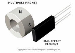
Magnetic sensors indirectly measure properties such as direction, position, rotation, angle and current by detecting the magnetic field and its changes. The first application of permanent magnet was a 3rd century BC Chinese compass, which is a direction sensor. Compared to other direct methods such as optical or mechanical sensor, most magnetic sensors require some signal processing to get the property of interest. However they provide reliable data without physical contact even in adverse conditions such as dirt, vibration, moisture, hazardous gas and oil, etc.
|
||
| The most widely used magnetic sensors are variable reluctance, Hall effect
and reed switch sensors. Automotive crash saftey systems use sensors based
on a holding mechanism that can be closed or open using electrical current.
With the rapid development of GMR in the past decade, a new family of magnetic sensors has emerged - magnetoresistive sensors. Similar to Hall effect sensors, the major difference is that MR sensors detect current change instead of voltage. Permanent magnets can also be used in MEM sensor and CMOS magnetic sensor arrays to supply the magnetic field. Dexter offers a variety of permanent magnet materials to suit your applications.
Material selection depends on the field requirement, temperature, environment
and cost. Please contact Dexter for assistance if you have special requirements
on the sensor magnet. |
| Introduction
Reed switches consist of two or three ferromagnetic blades (or reeds)
hermetically sealed inside a glass envelope. Operation Contact Protection Cutting and Bending |
| Reed Switch Structure |
|
| Reed Switch Characteristics |
|
| Special Precaution |
| 1.Reed Switch lead forming |
 |
||
2.Mounting (soldering and welding) |
||
|
||
3.Shock and vibration.
|
| Reed Switch and Permanent Magnets. Types of actuation. | |
|
| Permanent Magnet Actuation Patterns. | |
|
|
| Switch Tips: Reed switch basics |
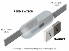
 A reed switch gets its name from the use of two or three thin metal pieces,
called reeds, with plated contacts at their tips and spaced a small distance
apart. The reeds are typically encapsulated in a sealed glass tube filled
with inert gas. A field from a magnet or an electromagnet deflects the reeds,
making or breaking switch contact.
A reed switch gets its name from the use of two or three thin metal pieces,
called reeds, with plated contacts at their tips and spaced a small distance
apart. The reeds are typically encapsulated in a sealed glass tube filled
with inert gas. A field from a magnet or an electromagnet deflects the reeds,
making or breaking switch contact.
Two-reed devices have normally open contacts which close when actuated. Three-reed versions have a pair of normally open and normally closed contacts. Operation of the switch causes these parts to change to the opposite state. An applied field makes the reeds magnetic so their ends attract. Removal of the field lets the springy metal reeds return to their original positions. The movement of the magnet relative to the reed switch determines how the switch toggles. Moving the magnet perpendicular to the side of the switch causes one switch closure per pass. Moving the magnet parallel to the switch provides as many as three closures with the maximum magnet travel. Another option is to spin the magnet near the switch. When the pole axis and the switch axis are parallel, the switch closes. When the axes are perpendicular, the switch opens. There are two or more closures with each revolution depending on the number of poles. Another typical scenario for a reed switch employed in position sensing is to either move the magnet near the switch or slide ferrous metal between the switch and the magnet, thereby toggling the contacts. Alternatively, the reed can be biased closed with one magnet sitting just inside the actuation distance. A second magnet can then open the switch by canceling the field of the first. Typical commercial-grade reed switches handle currents in the milliamp range on up to about 1 A of either dc or ac current. However, special designs can get to around 10 A or more by incorporating separate magnetic and contact units, thereby allowing optimization of the contact area. Reed switches frequently get incorporated into sensors and into relays. One of their advantages is a built-in hysteresis with regard to magnet position. For example, a magnet coming within range forces the switch contacts closed. They will stay closed as the magnet draws nearer and will remain closed until the magnet is out of range. One important quality of the switch is its sensitivity, the amount of magnetic energy necessary to actuate it. Sensitivity is measured in units of Ampere-turns, corresponding to the current in a coil multiplied by the number of turns. Typical pull-in sensitivities for commercial devices are in the 10 to 60 AT range. Reed devices can be obtained bare or packaged in plastic and aluminum
housings ready to install. Typical applications are in proximity sensing,
liquid level sensing, security systems, blood processing machines, baby
incubators, IV drips, and in current-sensing relays. A point to note is
that reed switches have a resonant frequency that relates to the length
of the reeds. Typical resonances are in the range of 2 to 3 kHz but can
depend on a variety of factors. |
Address: Rm1301-1302 No.5 Oriental Commercial Center,Xingning road, Ningbo City,Zhejiang, China |
Tel:
+86(574) 27861829 27861849 27861830
Fax: +86(574)87264906 |
E-mail:
[email protected] |
Copyright
©1995-2003 DSW Electronics Ltd. All rights reserved. |